What Are Analog and Digital Signals in BMS?
The Founder's Explanation (Teach Exactly This Way)
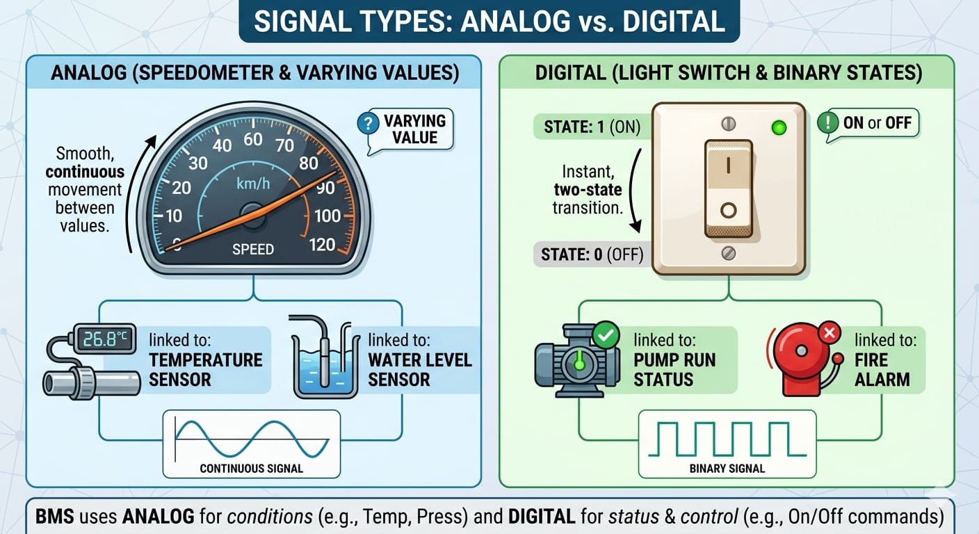
"Consider a speedometer — the value varies from 0 to 100 and even more, based on how much you press the accelerator. The value keeps changing continuously based on the input. Same way, consider human body blood pressure — it varies. Now come to BMS — here temperature, pressure, level varies in buildings like the human body. The human body has pressure, level, flow — it is called analog. If these signals are read by the controller — it is Analog Input. If these signals are given by the controller to the field to activate something — it is Analog Output.
Now come to digital. Like normal home switches — either ON or OFF, that is 0 or 1. That is digital. If the controller gives a command to the field — it is Digital Output. If the signal is received by the controller as input — it is Digital Input."
Teaching the Concept
The Speedometer — Analog
Your car speedometer does not jump from zero to 100. It moves smoothly — 15, 27, 43, 68, 91. It follows exactly where your accelerator takes it. It can be at any value within its range. This continuously changing value is an analog signal.
Your own body proves this:
- Blood pressure — rises when running, drops when sleeping. Always somewhere between values. Analog.
- Body temperature — varies through the day. Never fixed at exactly one number. Analog.
- Bladder level — builds gradually from empty to full. Analog.
In a building:
- Room temperature — 21°C, 23.4°C, 26.8°C. Always somewhere in the range. Analog.
- Water pressure in a pipe — 1.2 bar, 2.7 bar, 4.1 bar. Varies with demand. Analog.
- Tank level — 23%, 67%, 91%. Rises and falls. Analog.
The Home Switch — Digital
Your light switch has exactly two positions. ON or OFF. There is no in-between. No 47% on. Either 1 or 0. This is a digital signal — two states only.
Whether a pump is running or stopped — two states. Whether a door is open or closed — two states. Whether a fire alarm is normal or active — two states.
Analog Input (AI)
When a sensor measures a continuously varying value and sends it into the controller:Temperature sensor 24.7°C → Controller AI-01
Pressure sensor 3.2 bar → Controller AI-02
Tank level 68% → Controller AI-03Analog Output (AO)
When the controller sends a variable command to a field device:Open valve to 65% → Chilled water valve
Run at 45Hz → Variable frequency drive
Position at 30% → Damper actuatorDigital Input (DI)
When the controller receives an ON/OFF status from the field:Pump running = 1 → DI to controller
Pump stopped = 0 → DI to controller
Door open = 1 → DI to controller
Fire alarm = 1 → DI to controllerDigital Output (DO)
When the controller sends an ON/OFF command to the field:Start chiller = 1 → DO from controller
Stop exhaust fan = 0 → DO from controller
Open motorised valve = 1 → DO from controllerSummary Table
| Signal | Direction | Carries | Example |
|---|---|---|---|
| Analog Input (AI) | Field → Controller | Varying measured value | Temperature 23.5°C |
| Analog Output (AO) | Controller → Field | Varying command | Valve at 65% |
| Digital Input (DI) | Field → Controller | ON/OFF status | Pump running = 1 |
| Digital Output (DO) | Controller → Field | ON/OFF command | Start fan = 1 |
Related Topics
- What is BMS integration? — how a BMS connects with VFDs, energy meters, BACnet/Modbus devices and other building systems
- How to design a BMS system step by step — the complete BMS design methodology covering site survey, IO list, controller selection, sequence of operations
- What is a Building Management System (BMS)? — fundamentals of BMS controls and architecture for HVAC, lighting, energy and access
- What is BMS commissioning? — the disciplined commissioning process that turns a BMS install into a working building brain
- Browse all IO List & Wiring topics — more from this section of the EnSmart BMS Library